
How to Identify Screw Wear
21 Mar 2025
Tips and Techniques
Screw Wear:
Understanding the Causes, Effects and Solutions
How to find out what has happened to your screw and what to do about it.
Screw and barrel wear is a serious issue for maintenance and engineering departments in both extrusion and injection molding, and for good reason.
Screw and barrel wear is a serious issue for maintenance and engineering departments in both extrusion and injection molding, and for good reason. Excessive wear in a plasticating unit brings a long list of problems with inconsistent output (throughput), which directly affect the cost and overall quality of the product being made. In an article in the February 2018 issue of Plastics Technology, asking "What Is Your Extruder Trying to Tell You?", the authors Wes Hobson and Mike Rutkowski of The Dow Chemical Company demonstrated the need for baseline data and wear monitoring in order to avoid excessive loss of output.
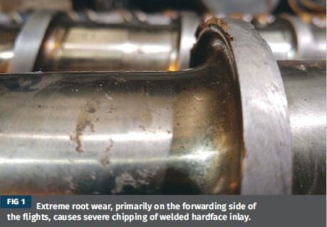
Image 1: Excessive screw wear, mainly on the pushing side of the flights, leads to severe grinding away of the welded hardfacing insert.
Hobson and Rutkowski did a great job of showing how to diagnose excessive screw wear through quality and throughput problems. Now that we have an idea of what extruders "tell us" from a processing standpoint, the next step is to investigate what is happening to the screw and what can be done about it. In this article we will look at how screw wear affects quality, and at the economics of repairing versus replacing worn equipment.
TYPICAL SCREW WEAR
Screw wear in extrusion and injection molding can be similar: in most cases wear occurs in high-pressure areas, in particular in the transition section and in the last few flights. Processors and suppliers commonly theorize that wear in these areas is caused by metal-to-metal contact between the flight OD and the barrel liner ID due to screw bending at high pressures. This theory is unlikely, since the internal pressure is generally the same along the length of the screw.
Most of the wear occurs in high-pressure areas, in particular the transition section and the last few flights.
A pressure differential is needed to build pressure in a particular zone, not a generally high melt pressure throughout the whole screw. Metal-to-metal contact may occur, but it is a result of mechanical conditions and is a symptom of potentially larger problems: misalignment, gearbox damage, a bent screw, a bent barrel, incorrect installation, and so on. Abrasion testing carried out in many industries shows that higher pressure and temperature lead to increased friction. Since the transition section and the last few flights of the metering section typically experience the highest pressures and temperatures, we can predict that this is where the bulk of the OD wear takes place. This has proven true empirically after inspecting and rebuilding thousands of screws.
As with loss of flight OD, root wear is usually the most severe in these high-pressure areas. Wear is more pronounced on the front (pushing) side of the flight than on the back side. The degree of root wear is strongly affected by the resin or resins being processed. When processing abrasive fillers such as glass fiber or calcium carbonate, severe wear can be seen in the feed section, due to the pressure generated by the pushing side of the flight, with limited lubrication provided by unmelted pellets. The amount of filler present and the particle shape strongly influence the intensity of wear. Larger particles with sharper corners tend to cause more wear than smaller round particles. Unfortunately, the desired physical properties of the molded part determine which filler to use. Since wear is more typical with fillers, they should be added downstream, where the polymer is already molten, to provide better lubrication.
Mixing sections and barrier flights also tend to wear, because their function requires the melt to flow exactly along the geometry of their flights. Dispersive mixing designs include some form of "undercut" geometry that forces the melt through high shear to improve melt isothermality and color uniformity (i.e. overall melt homogenization). As the mixing design wears, adequate dispersion is lost. Like dispersive mixers, barrier flights are cut to separate the melt pool (between the flights) from the solid bed (directly on the flights). As these special mixing sections wear, barrier designs can lose smooth feeding and mixing efficiency.
THROUGHPUT PROBLEMS
Screw wear is generally a slow process that can go unnoticed until throughput drops significantly. Minor wear has little effect on overall output, since machine settings can be adjusted to maintain it. When the radial clearance between the screw and the barrel wall increases, a pressure drop and incorrect melt passage over the flights are inevitable. The operator usually sees reduced throughput and higher melt temperature, which leads to higher rpm and energy consumption to maintain the desired rate. As the radial clearance grows, the screw cannot generate the feed pressure needed to maintain the required output.
Clearly, the size of the radial clearance is a key variable in leakage calculations. The usual rule of thumb treats a flight clearance of four times the original tolerance as the cut-off point for replacing screws, but it is important to take polymer flowability into account. A higher-viscosity polymer will give a smaller loss of output than lower-viscosity polymers at the same radial clearance. These rules of thumb should be treated only as guidelines.
To better predict the effect of diametral wear, you can calculate the leakage flow rate, taking into account the total clearance, flight width, strength, head pressure, viscosity and melt density. These calculations can become quite cumbersome when trying to predict throughput exactly; but reasonably accurate estimates that predict the potential loss of rate can also be obtained. To help processors and maintenance departments predict this loss of output, the author developed a rate-loss calculator that estimates the potential loss of rate due to screw wear. This tool helps to visualize the severity of wear and helps teams draw up a plan for replacing or repairing screws.
It is important to monitor screw wear before the likelihood of breakdown and energy consumption rise sharply.
This tool was used to generate the results shown in Tables 1 and 2, which show the estimated rate loss for PP and PE under the same conditions. Note that the more viscous PE gives less rate loss than PP. When processing other polymers that are sensitive to changes in design, such as PVC and PC, minimal wear can adversely affect quality because of the rise in melt temperature caused by excessive wear.
As the polymer flows over the flights, the material experiences excessive shear rates. This raises the melt temperature, which is compounded by the higher rpm needed to maintain output, as noted earlier. Higher melt temperatures can lead to serious quality problems, because at these excessive temperatures the physical properties of molded parts drop significantly. When processing amorphous polymers, these high shear forces can easily burn and degrade the extrudate.
Heavy wear usually creates pockets and areas where material can stagnate and melt. This shows up as black inclusions in molded parts. Gradual degradation of the material can become a serious problem when processing polymers such as rigid PVC. PVC tends to form hydrochloric acid at elevated temperatures, which leads to excessive corrosive wear of the equipment. In extreme cases of wear, the pushing sides of the flights can be eroded away, leaving little substrate to support the hardfacing weld insert, as seen in Image 1.
Without support, the brittle hardfacing material easily breaks off, leaving rough edges, a reduced flight width, contaminated extrudate and potential damage to downstream components.
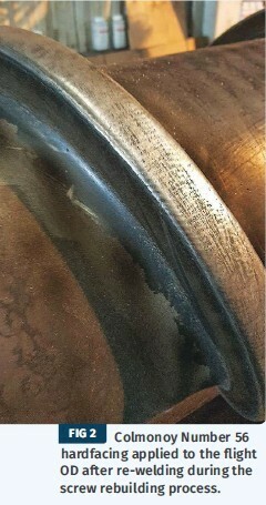
Image 2: Screw No. 56 with a harder metal surface coating applied to the flight OD after re-welding during the screw rebuilding process.
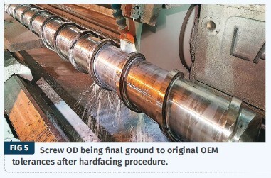
Image 5: The screw OD is finally brought back to the original OEM tolerances after the hardfacing procedure.
REPLACE OR REBUILD?
As many processors agree, downtime is the enemy of successful production. Many extrusion and injection molding plants rarely, if ever, stop machines to record wear. Tight production schedules and maintenance complications can push companies to squeeze the maximum out of existing equipment. The cliché "If it ain't broke, don't fix it" comes to mind.
The problem is that these options can put the processor in a situation where screw wear can no longer be ignored. Remember: screw wear is a gradual process that can go unnoticed until spikes appear, energy consumption rises and, in extreme cases, catastrophic poor performance results. To save the downtime and the costs associated with buying and installing new equipment, many processors spend a fortune hiding the costs of increased energy consumption and material waste. When the
screw is finally pulled for inspection, it cannot be salvaged, which leads to more downtime while waiting for new equipment.
The calculator estimates the rate loss due to the screw
Total wear: 0.016 in
(Average radial barrel liner + average radial screw)
Nominal screw OD: 3.5 in
Flight width: 0.3125 in
Screw: Normally equal to the nominal screw OD, not including commas, 3.5 in
Head pressure: 2000 psi
Material: Polypropylene
Melt index: from the material supplier, 26 g/10 min
Melt test load: 2.16 kg
Material melt density: From the material supplier
0.7 g/cm³
Estimated rate loss: 21.22 lb/h
Total wear: 0.016 in (Average radial barrel liner + average radial screw)
Nominal screw OD: 3.5 in
Flight width: 0.3125 in
Screw: Normally equal to the nominal screw OD, not including commas, 3.5 in
Head pressure: 2000 psi
Material: Polypropylene
Melt index: from the material supplier, 20 g/10 min
Melt test load: 2.16 kg
Material melt density: From the material supplier
0.7 g/cm³
Estimated rate loss: 16.323 lb/h
With baseline data, wear-monitoring procedures and an understanding of what is happening to the screws, technical and engineering departments can significantly reduce downtime and increase their profits. Replacing high-performance feed screws can be expensive, but an experienced screw manufacturer can bring worn screws back to like-new condition at a small cost in less time. When you want to rebuild a worn screw, ask yourself the following questions:
1. How severe is the overall wear?
2. What are the characteristics of the wear?
3. Can the current screw design be significantly improved?
4. Can the surface treatment be improved?
If wear is ignored despite careful monitoring, SCREW wear can become so extreme that it is difficult or even impossible to repair reliably. As a rule, the cost of rebuilding a screw depends on the severity of the wear and the amount of work required. An experienced screw manufacturer can evaluate the worn equipment and the production conditions to determine whether it is worth developing the current design. In some cases a new, optimized screw can significantly improve overall profitability. Often a worn screw can even be cut down, improving performance, instead of scrapping the old screw. To improve abrasive and corrosive wear resistance, hardfacing and surface treatment can be upgraded to extend the overall service life of the screw.
Many reputable screw suppliers claim that a screw can be rebuilt only three or four times. Screw size and a number of factors that affect the severity of wear can strongly influence screw life, but it is not uncommon for an experienced screw manufacturer to rebuild a screw many more times. Thanks to high-quality welding, careful consideration of the metallurgical aspects of screw manufacturing and proper repair of the working profile, the author has seen screws rebuilt up to six to eight times.
After the screw is machined to a uniform flight diameter, the flights must be built up again using higher-hardness hardfacing alloys that provide maximum wear resistance (Fig. 2). After hardfacing, the screw OD must be machined to the original tolerances (Fig. 3). The remaining overhanging weld must be profiled to ensure minimal loss at the flight. In many cases poor practice reduces the effective flight width during this process, potentially affecting screw performance and complicating the potential for future rebuilding. To alleviate these complications, some screw manufacturers prefer to reduce the weld width. When these screws are ground to the original tolerances, the welded hard surface does not cover the full width of the flight surface. This adversely affects wear characteristics because of exposure of the softer base material.
DEVELOP A PLAN
With proper baseline data and wear-monitoring procedures, and an understanding of what is happening to the screws, technical and engineering departments can develop a quality maintenance program to significantly reduce downtime and improve profitability. It is important to monitor screw wear before the likelihood of breakdown and energy consumption grow into a problem. Do not throw away worn equipment too quickly. Consulting an experienced screw manufacturer about the possibility of rebuilding will help reduce not only downtime but also rebuilding costs, which are generally a fraction of the cost of a new screw. Good rebuilding methods should allow screws to be saved, which will significantly reduce maintenance costs. A successful
planned maintenance program based on baseline data, wear monitoring and a basic understanding of screw wear is much better than emergency maintenance.
ABOUT THE AUTHOR: Stephen Surley is a sales engineer in Texas
at R. Dray Mfg. Inc., hired by the company's president and well-known designer Wynn Robert Dray. Surley spent most of his time working closely with customers in both injection molding and extrusion to develop custom solutions to improve molding quality and efficiency.


