
Twin-Screw Extrusion – Maintenance
21 Mar 2025
Improving Screw Element Removal on Your Twin-Screw Extruder
This article covers everything you need to know to safely and efficiently remove,
clean, rebuild and reinstall the screw set of your twin-screw extruder.
What you will learn:
1 Cleaning and inspection. How to perform the initial cleaning and check for dents and cracks.
2 Rebuilding the assembly. Accurate positioning of components and application of anti-seize compound.
3 Reinstalling the screws. Make sure the gearbox output shafts and the couplings are in the correct position.
Improving Screw Element Removal on Your Twin-Screw Extruder
This article covers everything you need to know to safely and efficiently remove,
clean, rebuild and reinstall the screw set of your twin-screw extruder.
What you will learn:
1 Cleaning and inspection. How to perform the initial cleaning and check for dents and cracks.
2 Rebuilding the assembly. Accurate positioning of components and application of anti-seize compound.
3 Reinstalling the screws. Make sure the gearbox output shafts and the couplings are in the correct position.
Because process engineers move from one job to the next, time is money.
Twin-screw compounding extruders are all designed with replaceable elements whose arrangement on the screw shaft is configured to optimize the process. When a run is finished and it is time to move on to the next one, the screw set must be removed and pulled out to make way for a new set.
How quickly and efficiently this key task is carried out has a direct impact on the bottom line.
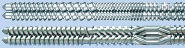
With this in mind, this article describes best practices that you should consider putting into use to speed up this process.
First – if at all possible – pull the screws immediately after use while they are still hot, or put the screw shaft assembly back into the extruder to heat the shafts and elements together. Letting the elements heat up slowly (about 20 minutes) is always better.
The idea is to remove the screw tips and place the screw assembly near
a lifting table or cart right at the end of the machine.
Always wear cut-resistant gloves (Kevlar or another cut-resistant fabric) when handling screw elements.
If the shafts must be removed from the machine and heated with a torch, take precautions and heat evenly along the entire length of the element. Do not let the element change color! This can affect the metallurgy. Warm them rather than burn them. Use a rosebud acetylene torch and be patient. While the elements are hot, use a punch made of wood or hard plastic to push the elements off the shaft. An aluminum or brass punch can also be used, but caution is also advised when striking the elements. The following steps will help considerably:
• Use heat-resistant gloves.
• Support the screw assemblies at enough points so that they do not bend.
• Unscrew the tips to remove the elements.
• While using the rosebud torch, pull the elements off the shaft.
• Higher-value elements need gentler treatment.
• Angle a suitable punch against the flight of the element.
• Use a rubber mallet and a hammer while heating until the element starts to move.
• Remove one element at a time and be sure to clean or scrape the exposed shaft.
For elements that are hard to remove, use an impact hammer – a noisy tool that works very well for breaking loose elements stuck to the screw.
Follow the screw removal steps above, with the following additions:
• Wear hearing protection.
• Change the receiving fixture of the brass tip.
• While heating, apply impact action to fight the element.
Cleaning and Inspecting the Screw Elements
You will probably get the best result by at least cleaning with a steel wire brush or copper mesh while the screws are removed from the machine. Once removed, you can put the elements in an oven or a fluidized
bath to clean them. But keep in mind the temperature rating of the metallurgy and do not exceed it. If the material is black, heat-treated or degraded, some form of mechanical abrasive cleaning will be needed to remove it. Brass or copper brushes are often too soft and will not remove heat-treated, degraded material. If this is the case:
• Wear gloves and eye protection.
• Use a dense wire brush buffing wheel on a bench grinder.
• Use a belt sander (small pneumatic handheld belt sanders work well).
• Use a sandblaster or a dry-ice blasting unit.
• Clean the keyways and splined bores.
Once the elements are clean, inspect them for micro-cracks and any dents or grooves. Dents and grooves can turn into cracks and should be gently smoothed with a needle file or a grinding wheel.
In addition, the end faces should be "stoned" or sanded with 320-grit sandpaper. This should be done on a flat, machined surface such as a marble slab or thick steel plate.
Lay the emery cloth or 320-grit sandpaper flat on the surface and work the outer surface of the element in a figure-eight pattern, applying only enough pressure to clean the face of the element evenly. If wear is evident, the dimensions should be checked with a micrometer and recorded. Elements with micro-cracks must be rejected. Damaged elements break during operation, which shows up as twisting of the shafts and barrel failures, and they cause catastrophic gearbox damage.
Remember that there is a butt-joint gap between the screw elements. The permissible tolerance between elements is very tight, but it must be visible. A flashlight can be used to confirm visibility and to check that the line of light passing between the elements remains constant.
Rebuilding the Screw Shaft Assembly
Screw components have sharp edges and can cause injury if moved incorrectly. Always wear Kevlar gloves or gloves made of cut-resistant fabric when handling screw elements. Some additional tips:
• Clean the shafts with a wire bottle brush to remove any remaining foreign material. This also includes the splined connections.
• Inspect the screw elements and use the procedures above to clean off foreign material.
• Anti-seize compound must be used every time elements are mounted on the shaft. A suitable one is Gleitmo 820 (fuchs-lubritech.com). It is a white grease that does not break down at high temperatures.
• The anti-seize compound should cover the entire surface of the shaft, but use it sparingly (rub on, wipe off). Anti-seize compound that gets onto the end face of an element during installation on the shaft must be removed.
• Lay both shafts out as a pair parallel to each other. If a shaft clamping device is available, use it to hold the shafts in the correct timing position.
• If a clamp is not available, clamp the shaft ends between two wooden boards at the correct shaft center distance.
• Screw elements are installed in pairs. The corresponding position between the screw elements and the shaft set screws must be correct (in sync).
• Once the first pair is correctly oriented, the remaining elements are arranged "face to face." Usually the first pair is moved back toward the end of the shaft so that the end profile of each element can be aligned and they match up.
• Mount the screw elements on the shafts following the layout drawing.
• Complete the screw-to-shaft assembly by threading on a pair of screw tips and tightening them by hand. Final tightening is done after the screws are in the extruder.
Tools and parts recommended for your maintenance shop.
Note: Work carefully, wiping the end faces of the element each time it is turned.
Double-check their fit, especially on splined shafts. All this will ensure that the screws can rotate properly when assembled and will speed up reinstallation of the whole assembly.
• Assembled screws can be double-checked by ensuring the gap between the assemblies in the set, positioned consistently. The permissible tolerance between elements is very tight, but it must be visible.
A flashlight can be used to confirm visibility and to check that the lines of light passing between the elements remain constant.
• Install the screw-shaft couplings on the screw-shaft assembly,
gearbox output shafts.
• Coat the shaft splines generously with anti-seize compound.
Once the assembly has been checked, lay the two screws and the gearbox couplings on a flat table or floor so that the coupling sleeves meet properly and are in the correct position, and rotate the screw set forward and backward while watching for incorrect meshing (this applies only to co-rotating screws). Incorrect
installation of the element set either rubs the screws together or pushes them apart where they mesh.
Reinstalling the Screws in the Extruder
To reinstall the assembled screw-shaft units, first make sure the gearbox output shafts and the couplings are in the correct position: offset by 180°, which means the set screws or coupling pointers face outward at 9 and 3 o'clock. To rotate the gearbox output shafts, either turn the primary motor coupling by hand (with the mains power switched off and locked out) or turn the motor very slowly using the drive. Orient the screw shaft ends in the same direction
(9 and 3 o'clock), and hold the two screws close to each other so that they mesh. At this stage:
• Remove any solid material from the barrel bores.
• Vacuum all loose debris from the connecting passage and the barrel bore.
• Make sure the barrels are precisely aligned.
• Visually check for possible mutual interference between contacts, adapters and devices.
• Insert the synchronized screw-shaft assembly straight and parallel.
• Do not push the shafts further if you feel any interfering resistance.
• Once the screw-shaft splines are clear of the seal washer, coat the splines with anti-seize compound.
• Push the assembled shaft through the remaining distance in the coupling.
• Complete the installation of the screw-shaft assembly.
When the screws are fully engaged in the couplings, check that both screw tips protrude through the end flange of the barrel by the same distance. If not, something is wrong, and the screws must be pulled out and the assembly checked.
At this stage, make the final tightening of the screw tips using the tip wrench supplied with the machine. Remember that the tips have a left-hand thread on an extruder rotating in the
same direction. Tighten each tip before the gearbox/motor starts to rotate – tighten fairly firmly. Do not use any "pipe extensions" on the tip wrench to tighten the tips harder. As a final check, at a very low speed setpoint (1–2 rpm), start the main drive and rotate the screw set a few turns. If everything seems fine, increase the speed to 20 rpm and listen for any knocking sounds. Slight clicking sounds are normal because the screws/barrels are dry. When material enters, the clicking usually stops.
About the authors: Bert Elliott has held various manufacturing and engineering positions in extruder manufacturing since 1981 and has been Technical Director at Leistritz since 1993. Over the last 30 years, he has taken part in more than 1,000 extruder installations, including many in the Far East.


